Blog Image

Thumper Diaries

About the blog

This blog is to be a diary of our activities and the trials and tribulations of owning a Royal Enfield Bullet 500. Your comments are welcome but there is a spam filter.
I hate spam.

For spares and such, I normally go to Hitchcocks Motorcycles

For a complete log (linked index) of all the posts in this blog, go here: Diary log

Standing Room Only

Customisation Posted on Fri, April 10, 2020 21:25:08

Thumper lives in my shed. It isn’t the worlds largest shed and I need to stand at the bench to get anything done. It has always been a bit of a squeeze with Thumper up on his centre stand. Even when I put his front wheel up against the wall I lose a foot and a half of space when I pull him up onto the stand. I decided something had to be done.
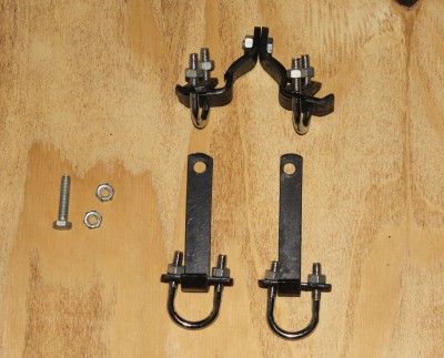
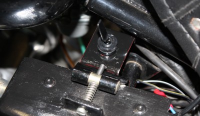
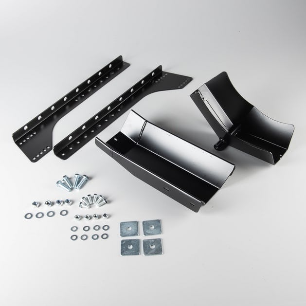
Normally, I reverse him onto the shed. I thought that if I had some way of parking him with the front wheel right up against the wall then the problem would be solved. A transport stand fixed to the wall might be a solution. The internet is my friend so I went off to investigate. I found one and ordered it. Cheap, cheerful and Chinese it may be, but it is a solid piece of kit. Some assembly required, as can be seen here:

I found one of the pillars that support the wall of the shed. Not easy, because the shed is insulated, and screwed the now assembled transport stand to it. I decided it wasn’t going to be stable enough with just the one small screw so I drilled through the front end of the “shoe” and set another, heavier, screw to secure the thing. Then I pushed Thumper forward into the stand. He went in with no problem and a satisfying mechanical clank as the shoe fell into place holding the front wheel. The stand is adjustable according to wheel size but luckily I had guessed right and no further fettling was required.So there he was, up against the wall and I had the space I required behind him to use as I please.

Although he is held in place by this thing I decided it wasn’t particularly stable with respect to sideways movement. He was in danger of tipping. One usually uses straps in conjuction with these stands. Now I understood why.
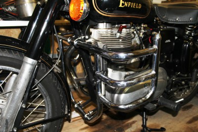
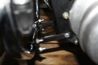
I don’t have anywhere to fix straps. My solution was to construct a stand offering support beneath the crash bars. I measured up and found some solid timber in my stache. An hours work and the job was done. Here’s the result:

So there it is. Thumper is nicely parked up against the wall and I have gained 18 inches of work room at the other end. I wasn’t so much worried about him tipping as I don’t usually touch him when he’s parked but accidents will happen and my Grandson is often in the shed with me. I could hold Thumper if he falls, but a youngster wouldn’t have a chance. A biproduct of the whole exercise is, that I now have an alternative stand to use if I so need it, because my constructed stand could be used anywhere.
Now that’s flexible design for you…


Saving the GPS

Customisation Posted on Tue, June 19, 2018 21:46:13

I’d almost given up on the GPS. The mounting box had suffered a short circuit which I am sure contributed to my battery problems, so I stripped it all out.
The GPS unit is still working though, so I thought I might try to find a way to remount the thing and run it off a USB cable. There had to be a way.
I’ve always liked the idea of having the GPS central to the handlebars. So that became the focus of my efforts.
There are two large bolts holding the bars in place. I could perhaps use those as mounting points. I needed a plate to mount the GPS on and something to work as a mount for that unit. I still have the old mounting block for the GPS even if it is useless. I stripped it all down and removed the old mounting block from the ugly set up it once hung on.
The back of the block has four screws to secure it onto anything I decided to make. I went off to the drawing board- Here’s the result:


I had the steel plate, a pillar drill, files and a hacksaw. I had to buy 5mm screws, washers and a length of aluminium tube with an internal diameter of 5.5 mm to fashion the spacers. The measurements were tricky but I hit the target every time so very little fettling was required to assemble the whole gadget. The spacers are necessary to allow clearance for releasing the locking mechanism which holds the GPS unit in place.
Removing the bolts on the handlebar mount is not as straightforward as one would assume. The tensioning bolts under the bars have to be released to allow the large top bolts to be removed easily. After that, fitting my plate was easy.

This is how it all looks:


The mount from above:


And with the GPS unit in place:


I can see over the GPS to look at the ammeter. The unit does not get in the way of the ignition and it is all pleasingly far way from the tank. I’m pleased with the result. If this doesn’t end the GPS saga, then I’ll drop the whole idea of having a GPS on Thumper..!


Lockable Storage

Customisation Posted on Mon, May 15, 2017 15:35:35

I decided I needed more storage space on Thumper. The tool boxes are OK, but when I go out for the day I need more stuff than I can load up with. Brew kit, camera, a snack or two, all builds up and I’m not much for wearing a backpack. Looking for an answer to this quandary I found a money box on the great interweb. It measures 300mm 217mm and is 100mm high. That would fit perfectly on the carrier rack. Cost, around £10.00. I ordered one. Here it is:

So the big question is; How to fit it to the rack?

As anyone with half an eye can see, the two central crossbars on the rack are offset toward the left of the picture. They are 16mm in diameter and 105mm apart.
I bought some pipe clips that (luckily) fit exactly round them and decided that would be the best way to mount the box. So a good deal of measuring is involved here. The screw holes are 35mm apart on the clips and I need to position four of them. The rack is slightly longer than the box and slightly not as broad. Technical drawings are not my forté but here, for the sake of explanation and the curious, are my drawings. The top one being the template for the holes and the second is my idea for attachment of the box to the luggage rack.

So, armed to the teeth with confidence and power tools, I can do this.. but not until tomorrow. I’m waiting for the box to be delivered. Logistics. What is one to do?

I’ll be back with an update and more pictures tomorrow.

The following day..
The box arrived in the afternoon. So much for getting up early to greet the postman…

Hurriedly unpacked, I set off to the iShed to get cracking. The inner shelf in the money box was of no interest to me in this instance, but it will make a great screw holder.
I bored the holes according to my excellent template and hey presto, it fitted exactly. OK, the bolts are a bit too long and protrude into the box but I can fix that with the Dremel cutter at a later date.

There is room for my camera, a small thermos flask, a packed lunch and a bit more besides. Maybe spare cables and the like. Just to complete the picture series, here’s a few shots of the finished job.

Happy bunny. I’m pleased with the result. OK, it won’t replace a full bodied top box but that was never what I wanted. This just gives me that little extra storage space I need for a day out in the cuds or shorter journeys to friends and family.

Hopefully, I can try it out very shortly.


Name Tag

Customisation Posted on Mon, November 07, 2016 14:21:13

I decided that Thumper needed a little more decoration on the front end. What better then, than to get him a name tag? I found an online press that makes transfers to order and got busy.
For the paltry sum of eight quid, I ordered the transfer which you can see in the picture below. It was a bit tricky to get it to curve with the mudguard but with a bit of fine fettling, it finally went on in one fell swoop.

Now everyone will recognise Thumper.


Crash bars

Customisation Posted on Thu, March 10, 2016 12:58:27

The one thing you hope you’ll never need.

I ordered a wrap-around type, mainly because I liked the look of the thing. It came complete with a fixing kit and no instructions. I suppose these things should be self explanatory. Here’s a picture of said kit, in all it’s glory, laid out as I think it should be.


I think I am missing a couple of nuts and bolts..

The two long brackets fit to the lower end of the frame. The bent bits at the top bolt together and pinch the frame just beneath the fuel tank. Don’t forget to release any cables from their plastic ties before you put this on.

Now one needs six hands but has only two. Which is frustrating to say the least. The trick is to mount the brackets and not tighten anything up. Juggling with the ‘u’ bolts and the brackets is not easy but gradually tightening the grip as you go will eventually pay off. Centre the whole shooting match up before finally tightening all the nuts.

Re-tie your cables.

Clean up and put the tools away.

I had to move my pump but found a spot on the crash bar where I could re-attach it.

All in all, I’m happy with the result. Now I only have one worry. The shed door isn’t exactly wide. I have to wriggle Thumper out and more so on the way back in. I hope there’s room enough..!!

Here’s a picture or three.. OK, the second one isn’t very clear but I’m sure people will get the gist of what’s going on.


Re-wiring the GPS

Customisation Posted on Fri, February 19, 2016 01:27:36

I know. I’ve already done the GPS thing. But I wasn’t happy about the wiring arrangement. It worked OK, but I didn’t like the thought of having it hooked directly to the battery, albeit with a switch between the two. I needed to find a wire to ‘T’ into that goes ‘hot’ with the ignition. The headlight nacelle is a birds nest of wires and I didn’t want to go in there. I’ve wrestled with this over the past year or so.

Then, a revelation!

Reading a post on the Royal Enfield forum, some bright spark pointed out that the horn goes hot with the ignition. That wire is easily found. Actually, there are two wires to the horn. One is live and the other is an earth, which goes to the horn button. Two minutes with the multimeter and I’d identified the one from the other.

I stripped out my original GPS set-up and simply re-routed the cable down the front of the frame and cut to length plus a bit. I clipped the horn wire and married the two ‘hot’ wires in a cable clip.
Obviously, this can’t be done on the earth side, otherwise the GPS would only work when the horn was being sounded, so I needed to find a good earth connection. Luckily there is a threaded end of a bolt protruding from my crank case so a simple connector could be placed there. Not being able to buy such a thing, I made one from a piece of thin steel plate and set it fast with an 8mm nut.

All connected up, I placed the GPS in its cradle on the bike and turned the ignition on.
Success! All works as it should.

I’ve since covered the connectors with shrink wrap. Looks really tidy now.

Here’s a few pictures of the wiring..


High Output Alternator

Customisation Posted on Fri, September 04, 2015 18:13:18

I was having problems with holding charge in the battery while out riding. I believe it is the result of having fitted electronic ignition and then adding a GPS. The problem really started with the addition of the GPS, which drains the battery within 35 Kilometres of leaving home. Switch it off and all is well. So I reckon the electrics were running at full capacity and the GPS was the tipper. After much deliberation, I decided to fit a higher output alternator. Beefing up the DC side can only be a bonus anyway, so the decision was made.

I found one in the Hitchcocks catalogue. Lucas. Stator and rotor. Expensive but necessary I thought. I ordered it.

I did some research. I’ve never refitted an alternator. I found a few video films on Youtube and asked around on the Royal Enfield forum. Feeling fairly confident, I set to work.

The footpeg and footbrake lever have to come off. Then the primary cover. The oil spill is spectacular. There is no drain plug on the primary so the cover comes off and the oil, well, ATF, just pours out along the entire length of the case.

I locked the primary chain in place with a block of wood wrapped in an oily rag. It’s easy, just rest the wood on the inside of the primary chain and turn the big nut holding the rotor in place. This action jams the wood between the chain and the sprocket at the clutch end and the whole thing locks up. I carried on and unscrewed the rotor. Then the stator. 3 nuts and don’t forget the washers. Then I disconnected the wiring from the loom and eased the wires out of the primary casing through the grommet. The stator can now be pulled. And then the rotor.

Time for tea and a fag, I thought. One has to nurture the inner man.

Duly revitalised, I returned to the shed and mounted the rotor. Again, use the wooden block to jam up the works and tighten the retaining nut. There’s a spring washer under that nut holding the rotor in place so give it no mercy and really get a good purchase.
On to the stator.
A note here. The high output stator from Lucas will require the OEM spacers on the mounting studs to be in place. I saw a video where the spacers had to be removed from the mounting studs due to the thickness of the stator.
I had also measured the diameter of the rotor and the internal diameter of the stator. The difference is 0,5 mm. Which means that one has 0,25 mm clearance all the way round. Not much to play with. Luckily, The Lucas stator has soft plastic or rubbery cushions fitted in the bore on either side of the pick up blocks that are the stator. So you don’t have to fiddle with feeler gauges. Smart. Mount and fasten the nuts and washers.

The wires leading from the stator should be on the outside and at the top. If you didn’t get that right, take it off and do it again. Then feed the wires out through the grommet.
The hardest part of that was getting the cable sheathing through the grommet. This required more tea and a little profanity. The truly frustrating part was, that the connectors on the wires were of a slightly larger size than the originals, which means one has to expose the female connectors and prise them open slightly to get a fit. Not easy with a confined space to work in and hands like shovels. Finally, it all fitted and the connectors were covered.

So far, so good. More tea, a smoke break and pat the dogs who had been following my progress with great interest.

Back to work then. While I was there, I adjusted the primary chain tension. Easily done and the primary case was off anyway, so why not? Cover on, brake pedal on, footpeg on. Then fill the primary with ATF and clean up the mess and tools.

Job done, I decided to start the machine. Thumper fired up on two kicks. The headlight works, the indicators work. I measure 13.2 volts at the battery at running speed. All seems to work.. Success…

..except the brake light and tail light. There is power to the brake light but it is weak. The tail light refuses to shine.

I’ll have to investigate… Oh, the joys of owning a Royal Enfield.

____________________________________________________________

Update: 06-09-2015

I found the problem. Just a loose earth connection to the rear light. I loosened it off, gave it a wriggle and, hey presto, I have lights again. This will need a more permanent solution later in the winter but it works for now.

Success..!!


GPS – Tomtom Rider

Customisation Posted on Sat, March 28, 2015 17:09:23

I got this for Christmas. I have one in the car but never thought I might have one for the bike. I didn’t think I’d ever need it. Still, not wanting to look a gift horse in the mouth I decided to fit the thing and see if it would prove itself to be useful.
The handlebar mount isn’t exactly elegant. In fact, it looks amateurish. If I was to design something to hold this expensive piece of kit, I would have put a design team on the job instead of presenting the almost bodge job that it is. Oh well, you use what you have. Here it is..

According the somewhat sparse instructions that follow the GPS, the only thing necessary, is to find a wire that goes live with the ignition on. Connect the live side to that and then find an earth for the other wire. I looked behind the headlamp at the birds nest of wires and gave up before even attempting to unravel it and identify the ignition wire. Hook it up to the battery, I thought. The damn thing can be switched off so no problem.

But then there was. A problem.

The screen unit sits on a plinth, or base unit or whatever it may be called. Even though the screen unit is switched off, the base unit draws a current. That current flattened Thumper’s battery in the run of a week. Here’s the base unit:


And with the screen unit fitted..

So… Plan B.
Simple, I thought, I’ll put a switch in between the base and the battery. I know that will work, but… where to put the switch?

Not wanting to clutter the headlamp nacelle more than it already is, I decided to mount a switch near the battery. I thought about using the battery box but decided there wasn’t room there, so the next idea involved making a plate to mount on the back of the battery box and place the switch there. That was simple to manufacture out of some thin steel plate and it is held in place by two pop rivets. Luckily, I have all the requisite tools and material and a little know how.

I measured the distance at which to separate positive lead and fitted spade connectors to fit the switch. The switch screws into the plate. A lick of Hammerite and the job is done.

Just to be sure it worked, I started Thumper and tried to switch the GPS on. Nothing.
Flicked the switch and bingo.. all worked as it should. Switch off and the GPS powers down.

Cracked it!

All I need to do now is plan myself a tour across the water to Sweden and take a weekend in the woods.. Bring on Summer. And, an added bonus, I can check my speedometer with the GPS.

More on that later..


Going Electronic

Customisation Posted on Thu, November 06, 2014 22:55:17

I’d heard a lot about electronic ignition. If you’re not the type who enjoys playing around with the ignition and points and so on then this may be the way forward. I’d heard that once fitted, you can forget all about it. Set it up once and that’s it. I went off to investigate..

I found a Boyer Mk4 electronic ignition unit at Hitchcocks. I rang them up. I’m not an electrical wizard so I needed some reassurance that even I could fit the thing if I bought it. I was told that even without the advanced strobe timing light and such, it was easily done if one followed the instructions that come with the unit. I was also told that any technical support, if needed, was only a phone call away. That said, I ordered the thing.

There’s not a lot to it. A sealed box unit of electronic wizardry with 5 wires hanging out of it, two plates, (one metal with magnets, one plastic with two coils and wiring hanging off said coils) and a bolt. It all looked innocent enough.

Instructions were simple enough too. Disconnect the battery. Then I had to dismount the saddle and my electrics cover to get to the coil. Then I had to identify the positive side of the coil. My eyes aren’t what they were but eventually I found a ‘+’ mark. So far, so good.
I mounted the unit in the left hand toolbox, drew the wiring out though the back of the toolbox and proceeded to hook it all up. One wire goes to earth, one to the coil, two to the electronic timing plate and one to the old wire that connected to the old points. That bit went well enough.
The points and auto advance mechanism has to be removed from the distributor and then you have to find top dead centre. I have a tool to help me with this.

Once found, the metal plate with the magnets gets mounted on the distributor spindle. Insert the bolt but don’t tighten it fully yet, according to the instructions. Then mount the plastic plate and set it up turned as far anticlockwise as it can be. Then you line up the magnets on the metal plate with the coils on the plastic plate so they all form a direct line across the plates. Tighten the metal plate and then rotate the plastic plate clockwise to midways between advance and retard. Tighten everything. That’s it.

With a good degree of trepidation, I decided to fire it up. Reconnect the Battery, fuel on, ignition on, kill switch to ‘run’, start help on and give it a swift kick.
OK, two kicks..
VROOM..!! Thumper fired up! Success. Woohoo! I ran round the shed with my arms in the air…

Then I had to reassemble the bike with all the bits I’d pulled off it to make the wiring and so on accessible, but what the hey, that was the easy bit.

I think I got lucky. I didn’t have to adjust anything or fiddle about with the plates to get the timing right. I think I was lucky enough to have hit the nail on the head at the first try, which is not something I’m used to but the simple result is that I converted Thumper to electronic ignition within hours and he runs like a good ‘un.

Which proves that even with as limited electrical skill as I have, anyone could fit this sort of thing.

Roll on Springtime…

Update 11/11/2014

I took Thumper out for a test run today. It wasn’t good at the start. Misfires and poor acceleration. I was ready for this and made roadside adjustments to the timing, advancing it slightly. The difference was tremendous. Ready response, even tick over and an eager engine that wants to run and run quickly. Had it not been so cold, I’d still be out there.
This is a success.


Lean and Mean

Customisation Posted on Thu, July 24, 2014 12:34:41

After having replaced the broken brake lever I decided it might be a good idea to get a side stand for Thumper. It may make getting on and off easier and it certainly helps when I need to park at the roadside.
I went for a big and sturdy part in chrome and fitting the thing took only seconds, which was a great relief as I had expected a heap of work to hang the thing on the bike frame.

There are no instructions that follow these parts so one has to look carefully at the possible mountings. The left hand side foot peg and spacer have to come off and the nut holding the centre stand. The bracket that carries the side stand then fits neatly on the two protuding studs, the spacer and foot peg are then replaced and the two nuts are put back in place. Nip it all up tight and the job is done. Never has anything been so simple.

My only complaint is that the side stand does make getting the centre stand down a bit more difficult as the ends of both stands almost touch. The manual does state that one should place the bike on the side stand before attempting to use the centre stand. I suppose that makes sense in some weird way but I would like to have the chance to make my own mind up as to which I prefer, depending on how and where I’m going to park. Not only that, but one has to think a bit before pulling away to ensure one has not forgotten to kick the side stand back up after using the centre stand..!! You wouldn’t want to corner hard to the left with the stand down.

Another point to note for all us amateurs; never run the engine for any length of time while the bike is on the side stand. It plays hell with the oil circulation as the oil in the sump is naturally draining away from the oil pump as the bike leans to the left.


Next »