Blog Image

Thumper Diaries

About the blog

This blog is to be a diary of our activities and the trials and tribulations of owning a Royal Enfield Bullet 500. Your comments are welcome but there is a spam filter.
I hate spam.

For spares and such, I normally go to Hitchcocks Motorcycles

For a complete log (linked index) of all the posts in this blog, go here: Diary log

Air!

Customisation Posted on Fri, May 09, 2014 22:17:00

I suppose I’m not the only one who worries about getting a roadside puncture. I have a can of that liquid puncture repair stuff that one simply squirts into the punctured inner tube through the air valve but how does one re-inflate the tyre? Not wanting to carry a large foot pump with me on my travels I needed something smaller but equally effective. I found it the other day. A cycle pump, almost like the ones available for push bikes. It is really compact, no more than 9 inches long, has a built in pressure gauge and comes complete with a mounting bracket which can be attached to Thumper’s frame. The bracket is great to have as the pump is too long to fit in the tool boxes.

Here it is:

Folded out and ready for use, it looks like this:

I mounted the bracket on the front of the frame with zip ties, allowing room enough to not foul the steering. I had to customize the bracket slightly to let the ties fit securely round it but, all in all, I reckon it turned out very well. It sits discreetly out of the way but is still easily accessible if I ever have the need to use it.


Charge!

Customisation Posted on Tue, April 15, 2014 17:13:26

Not that I’m storming into the middle distance with all guns blazing.. just that I wanted to make it a bit easier for myself if I need to put Thumper on trickle charge every once in a while.

Instead of having to remove the battery box every time, I have fitted two charging poles to the box and wired them into the battery terminals. Now I can connect the charger with a couple of banana clips and I can also check the voltage with a touch of my voltmeter. An added bonus is, that I have a 12v take off if I need it without having to get the cover off.

I separated them to each side of the box so I don’t risk dropping anything across the two poles and cause a short circuit. Negative on the left, positive on the right. The whole job cost me pennies and the only hard part was the soldering.
Here’s the result:

br>


Removing the PAV

Customisation Posted on Thu, February 06, 2014 16:29:29

What is a PAV? It’s a Pulse Air Valve that takes some unburned fuel and air mixture from the intake manifold and redirects it to the exhaust pipe just after the outlet port.
It is a device that supposedly will cause any unburnt particles in the exhaust to be burned and thereby reduce emissions. Nice, if it works. Which I don’t entirely believe.
If your national rules don’t require it, then neither do you. I don’t. So off it comes as it restricts the exhaust.

Removal is a piece of cake. No electrics involved, it merely unscrews from the exhaust pipe and the valve in the tool box. Unscrewing the armoured pipe will allow you to remove the valve from inside the box. The whole removal takes seconds rather than minutes. There are some resulting holes to be filled though.
One in the toolbox, one on the exhaust and one on the inlet manifold.

The inlet manifold is a bit of a quandry. I don’t trust the EU with their regulations and such so I decided to keep the little brass tube that works as the outlet from the intake manifold, intact. So I cut off a half inch of the neoprene tube that connected it to the PAV and screwed a slightly oversized screw into it. This becomes, effectively, a cap for the outlet which, by its removal, will allow me to reverse engineer the job if time and conditions dictate.

The toolbox was blanked by two oversized steel washers and a rubber washer, all held in place by a through bolt creating a sandwich of washer, toolbox, rubber washer and steel washer. The rubber washer is mainly for waterproofing. A dab of black gloss and the job is a good ‘un.

The exhaust pipe hole is blanked by a purpose made cap purchased from Hitchcocks.

For now, at least, my winter modifications are complete. I want to ride Thumper now I’ve done with the tinkering. A wash and a good polish is all he needs but that will have to wait until the sun is shining again.


Saddle Transplant

Customisation Posted on Sun, February 02, 2014 15:25:17

I couldn’t wait any longer. The cold weather has loosened its grip on us for a day or two so it’s off to the shed and get the saddle exchange done.

Getting the indigenous double seat off is easy. Four nuts and a quick pull on the sissy bar and it came away with no problems. The problems came later.
While I had the seat off, I fitted the electrics cover which obviously protects the wiring loom sitting directly beneath the saddle. It also helps to keep the bike looking tidy, so if you’re considering a seat change yourself, go the extra couple of quid and get one. It is well worth the investment.

Now, on to the refit. The saddle comes with a fixing set. Two plates, oblong, rounded corners, four bolts complete with washers and nuts and no instructions. The springs which hold the saddle up and cushion your ass are polished externally only and, again, no fixing instructions. So you’re on your own Jack. Deal with it.
The nose end of the saddle has a mounting on the underside comprising of a metal tube on a fixed axle and a bolt welded centrally. The nut which holds this in the fixing bracket will fit into the bracket but one cannot get a spanner to it to tighten it. The bracket works like a housing which absolutely encloses the nut and when fitted, there is no access to the nut, so I tightened as much as I could with my finger tip and that will have to do.

The springs mount on the saddle retaining studs which are too short to go through the electrics cover, the spring and the fixing washers. Next job then, is to loosen the studs and screw them as far out as one dares and then mount the spring. The spring is cunningly designed so as to not allow a grown mans finger to get in between the coils and maneouvre said washers and nuts. Frustratingly so. This is valid for both ends of the springs, which leads to some fairly colourful language when you get to fit the fixing plates underneath the saddle. Gravity is always against you in these situations.

I finally got it all in place but not without tea, cigarettes and a good deal of cursing. I’m pleased with the result but I believe there must be an easier way to fit these things. Maybe I should get my inventor hat out and see what I can do.

Anyway, here’s the result:

After I’d posted this, one of my online friends pointed out that I may just have gotten things a little wrong. As my father would have said in his day, it’s all ass over tit.
The fixing plates should mount on the seat studs, the springs should be mounted directly under the saddle and the fixing plates adjusted radially to accommodate a more upright stance for the springs under the saddle.
I did as Pete suggested and it all makes much more sense now! So he gets a mention in dispatches here and if ever I run into him, he’s good for a pint or two. Here’s what it should look like:


The Cover Up

Customisation Posted on Fri, January 31, 2014 12:53:53


The madness continues after the air filter rebuild. Having removed the old air filter box the resulting void left my electrics rather exposed and left the bike looking untidy. I’d had a bit of a winge about this on the Hitchcock forum and some bright spark told me that there was a cowling that could be fitted to cover the coil and exposed leads and tidy up the appearance of the area behind the carburettor and air filter.

I thought, ‘Gotta have it.’, so the hunt was on again for parts for Thumper.

I soon found it and, while I was at it, I ordered a single saddle and a top cover for the electrics which will, eventually, sit under the saddle when I re-fit. At the moment, the weather is so cold and that includes the inside of the shed where Thumper lives, that I may not get around to changing the saddle just yet.

But I digress. Having received all the bits in the post, I decided that this simple little job of attaching the cowling would be easy. It was, but one has to remove the toolbox to get at the fixtures, so the job took a bit longer than I thought it would. That is not difficult, but with freezing fingers, it took its time. It isn’t the removal that’s tricky, it’s putting it back where it came from that gets you!

The cowling sits on the old filter box mountings and one of the toolbox supports doubles up as the top fastener. Fitting was relatively simple and the whole job was done in well under one hour. The end result is impressive and elegant. Gone is the gaping hole where the old filter was and the coil and leads are neatly tucked away from the vulgar gaze. Aesthetically pleasing.

Had I known about this cowling before I changed the air filter, I would have ordered the whole kit at a single stroke and saved a bit on postage costs. Chalk one up to experience.

I hope you’re all taking notes…


Air on a G-string

Customisation Posted on Thu, January 16, 2014 20:57:02

Or something very close.

I’d been toying with the idea of actually using the right hand tool box as a tool box instead of an air fiter housing. Two options are available. One is to rebuild the tea caddy-like filter box and the other is to fit a conical air filter directly to the carburettor. I opted for the latter.

I found an S&B conical filter that comes with an optional shroud which offers some protection from the rain and other evils. Having checked that it will fit the carb, I ordered the two parts and set about rebuilding the machine.

Actually, it wasn’t that simple.

If one changes the air intake from the restrictive system it was to the open free draw that it now is, one also has to re-jet the carburettor. If it draws more air, then it needs more fuel, otherwise it will run lean and destroy the piston.

So I had to re-jet. I rang my suppliers of all things good and we agreed on a jetting that would solve this issue and parts were duly dispatched.
This meant I had to pore over technical notes as I’ve never stripped a carburettor before but after reading it all through a couple of times, I felt reasonably confident about tackling the job.
In fact, that bit of it all was easy. I removed the carburettor from the bike, re-jetted the carburettor, found and fixed a fault with the choke locking mechanism and fitted the filter and shroud, all in about thirty minutes. Not bad for a newbie, I thought. Proud of my achievements, I refitted the carburettor and attempted to start Thumper.

So, fuel on, ignition on, engine set to run, choke and kick. Three kicks and he was running. Yay! Success.
The subsequent road test went well too.

Only one problem niggled at me now. The carburettor is only supported by the rubber connector between it and the cylinder. It sort of dangles in the air and bobs about a bit. Actually, I could hear the carb knocking against something under the tank as it moved about. I decided I needed to support the filter side of the carb.

There is no part to be found that will do this. So I had to fabricate a bracket and figure out how to mount it. The tank retaining bolt is slightly behind the carb and the filter shroud is mounted to the filter by the large jubilee clip which holds it in place. This fortunate coincidence provided my two points of contact.

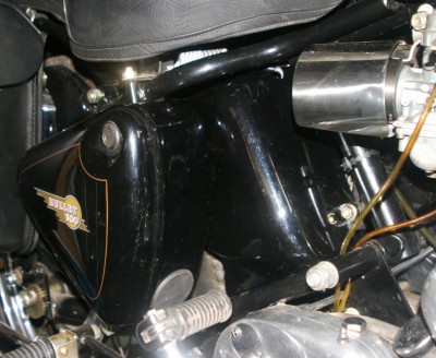
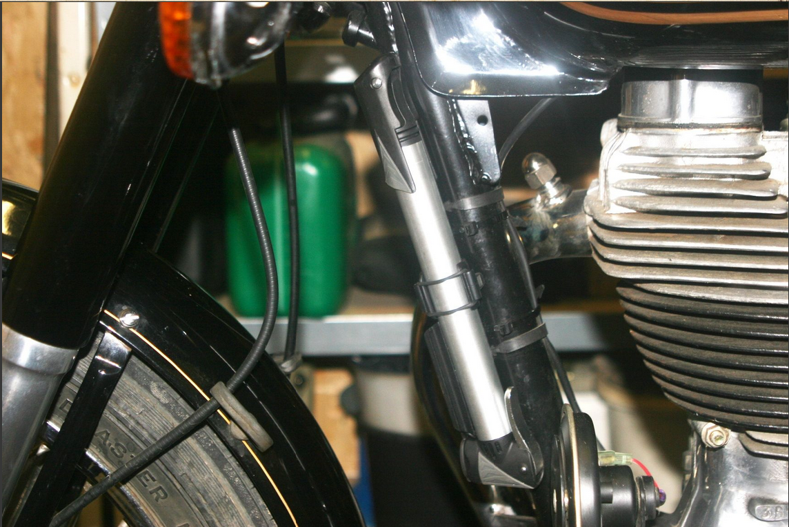
I bought some aluminium strip and set to work with a bench vice and a pillar drill and finally made the resulting bracket. Here’s a picture of it, in situ.

The whole thing sits very solidly in place now and the carb no longer jumps about. Cost? Pennies.

The right hand tool box is now fulfilling the purpose I wanted it to. The holes that fed the air ducting have been blanked off and I can fill the box up with tools, cables and other spares that may be needed on longer trips.

Sometimes, I even amaze myself!


The Time of My Life

Customisation Posted on Mon, January 13, 2014 18:44:50


Here’s a handy little add-on to your Bullet.

I got it from Hitchcocks and it didn’t cost me a fortune. You know how hard it can be to see your watch when you’re wearing gloves and tearing down the road at 50mph, so here’s the answer.

The clock sits over the fork nut on the headlight nacelle and screws fast with a tiny allen screw.

The one pictured above is black-faced, but mine’s white so I can see the time easier. I’m getting old.
Needless to say, I nicked the picture from H’s catalogue. Hope they’ll forgive me..!!

This could be very helpful on long haul trips. I tend to pace myself, riding for an hour, or whatever suits me and then take a break, light my pipe, pee, eat, drink my tea or anything else I need to do and then continue on again.

It’s not that I’m obsessed with time, in fact I have all the time in the world now, so I don’t have to care how long it takes to get from A to B but I do like to know how long my ass has been in the saddle at any given time.


« Previous